Modern pedal position sensors
| Vehicle | # of wires | APPS1 volts range | APPS2 volts range |
|---|---|---|---|
| 350Z/370Z/G35 | 6 | 0.15v - 4.6v | 0.15v - 2.5v |
| Audi S4 2010+ | 6 | 0.32v - 4.75v | 0.32v - 2.6v |
| BMW 335i | 6 | 0.32v - 4.75v | 0.32v - 2.6v |
| Dodge Challenger 2008+ | 6 | 0.32v - 4.75v | 0.32v - 2.6v |
| Mazda Miata 2006+ | 6 | 0.32v - 4.75v | 0.32v - 2.6v |
| Mitsubishi Evo X | 6 | 0.32v - 4.75v | 0.32v - 2.6v |
| Mustang 2005+ | 6 | 0.32v - 4.75v | 0.32v - 2.6v |
| Subaru WRX 2008+ | 6 | 0.32v - 4.75v | 0.32v - 2.6v |
| Toyota FR-S | 6 | 0.32v - 4.75v | 0.32v - 2.6v |
| VW GTi | 6 | 0.32v - 4.75v | 0.32v - 2.6v |
These are typically 6-wire Accelerator Pedal Position Sensors (APPS) used in drive-by-wire (DBW) systems. They contain two independent potentiometers that provide redundant position signals for safety and reliability.
Each channel senses voltage/resistance variation between the 5V supply and sensor ground. The ECU interprets these as pedal position voltages. The two signals are continuously compared — if significant disagreement or abnormality is detected, the ECU disables the sensor input and illuminates the Check Engine Light (CEL).
• Most modern DBW vehicles use 6-pin APPS sensors with two independent signal channels
• Two signal wires — commonly one rising (e.g. 0.5V → 4.5V) and one falling, or different voltage ranges (e.g. 0.5–4.5V vs 0.5–3.0V)
• Always consult the specific sensor datasheet or service manual for exact voltage ranges and behavior
• 5V supply and sensor ground — usually two of each for redundancy (connect exactly as in OEM wiring)
• Signal wires connect directly to ECU analog inputs — no pull-up resistor is typically required
• 4-pin APPS versions exist on some early DBW vehicles (e.g. 2001–2005 IS300) — these function similarly to a conventional 4-pin TPS with only one signal output
• Redundancy purpose: ECU monitors both 5V references, both grounds, and both signals — any fault can trigger limp mode or CEL
Input the exact volts vs. pedal % (or °) calibration table into your ECU for accurate throttle control and safety monitoring.
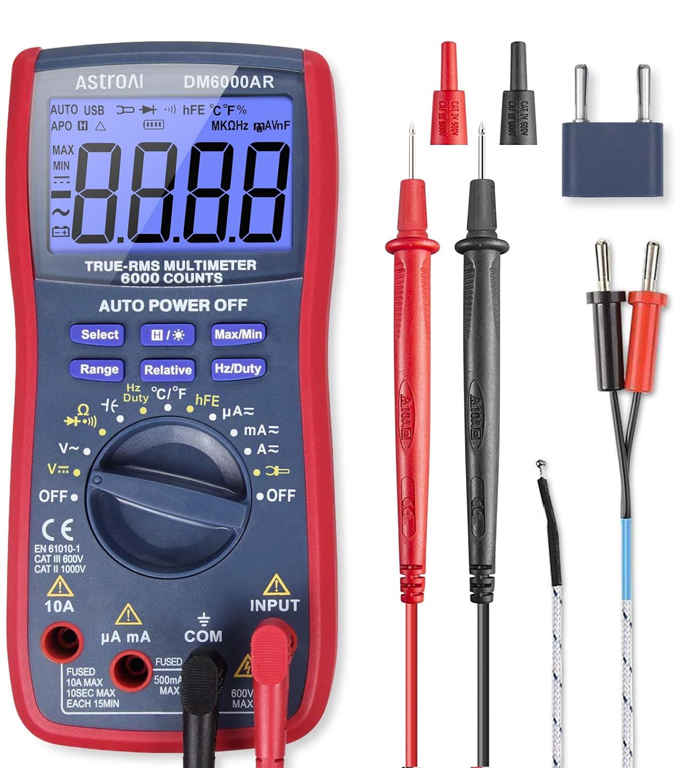
AstroAI Digital Multimeter and Analyzer TRMS 6000 Counts Volt Meter Ohmmeter Auto-Ranging Tester; Accurately Measures Voltage Current Resistance Diodes Continuity Duty-Cycle Capacitance Temperature
Buy on Amazon As an Amazon Associate I earn from qualifying purchases
8Pcs Crimping Tool Kit for Heat Shrink Terminals, Non-Insulated, Open Barrel, Solar Conncetors, Insulated and Non-Insulated Ferrules
Buy on Amazon As an Amazon Associate I earn from qualifying purchases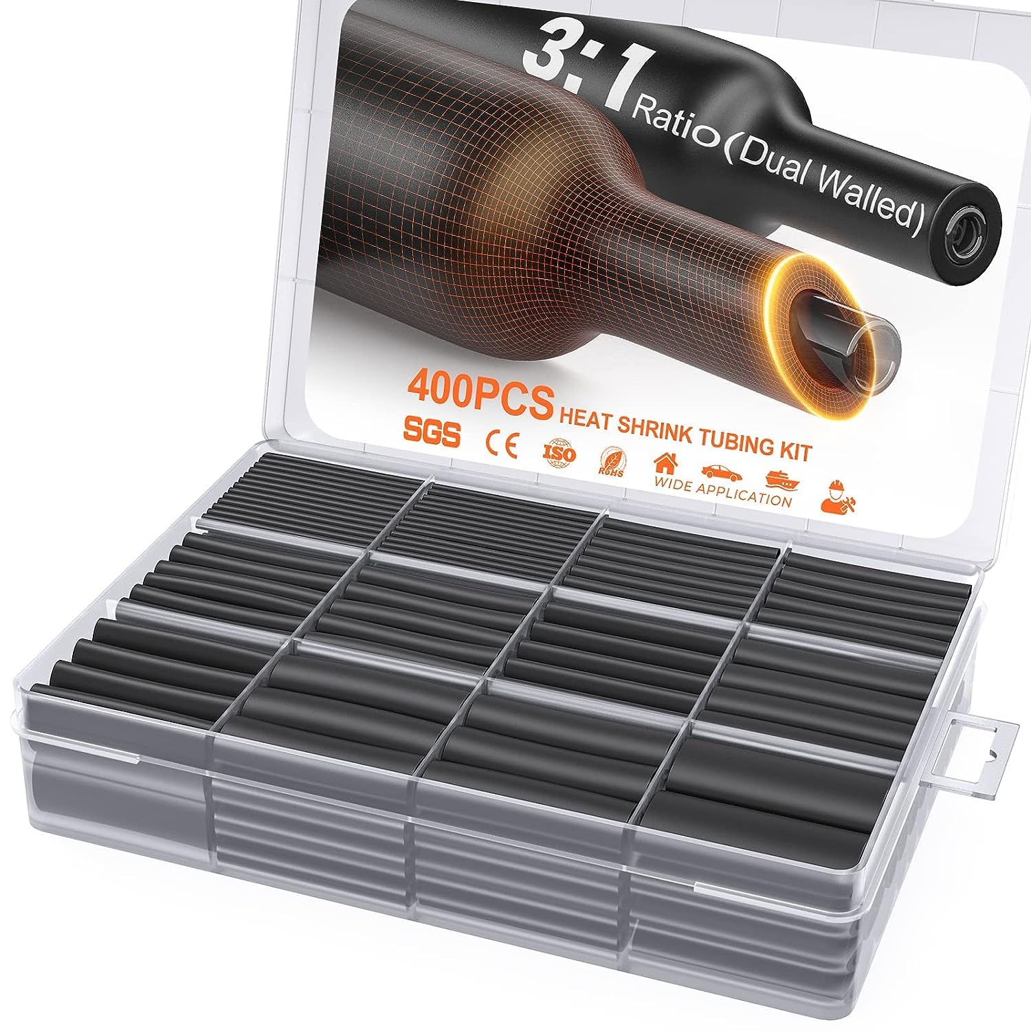
400 Pcs Heat Shrink Tubing Kit-3:1 Ratio Adhesive Lined,Marine Grade Shrink Wrap - Industrial Heat-Shrink Tubing - Black
Buy on Amazon As an Amazon Associate I earn from qualifying purchases
SVAAR 380PCS Non Insulated Butt Connectors Kit Butt Splice Connector Uninsulated Wire Splice Connectors for 26 to 6 Gauge Wire Marine Grade Tinned Copper Seamless Barrel Crimp Butt Splice Terminals
Buy on Amazon As an Amazon Associate I earn from qualifying purchases
3M Scotch Super 33+ Vinyl Electrical Tape, .75-Inch by 66-Feet
Buy on Amazon As an Amazon Associate I earn from qualifying purchases
AstroAI Digital Multimeter and Analyzer TRMS 6000 Counts Volt Meter Ohmmeter Auto-Ranging Tester; Accurately Measures Voltage Current Resistance Diodes Continuity Duty-Cycle Capacitance Temperature
Buy on Amazon As an Amazon Associate I earn from qualifying purchases
8Pcs Crimping Tool Kit for Heat Shrink Terminals, Non-Insulated, Open Barrel, Solar Conncetors, Insulated and Non-Insulated Ferrules
Buy on Amazon As an Amazon Associate I earn from qualifying purchases
400 Pcs Heat Shrink Tubing Kit-3:1 Ratio Adhesive Lined,Marine Grade Shrink Wrap - Industrial Heat-Shrink Tubing - Black
Buy on Amazon As an Amazon Associate I earn from qualifying purchases
SVAAR 380PCS Non Insulated Butt Connectors Kit Butt Splice Connector Uninsulated Wire Splice Connectors for 26 to 6 Gauge Wire Marine Grade Tinned Copper Seamless Barrel Crimp Butt Splice Terminals
Buy on Amazon As an Amazon Associate I earn from qualifying purchases
3M Scotch Super 33+ Vinyl Electrical Tape, .75-Inch by 66-Feet
Buy on Amazon As an Amazon Associate I earn from qualifying purchasesModern 6 wire TPS sensors
Throttle position sensors (TPS) on most systems produce very similar voltage readings, but always double-check values against your specific sensor datasheet or manufacturer specifications.
Most TPS sensors operate in opposing (complementary) fashion: as the throttle opens, one signal voltage rises while the other falls. This redundancy is especially common in drive-by-wire (DBW) applications for safety monitoring.
5V supply and sensor ground:
Drive-by-wire systems typically feature two separate 5V reference supplies and two sensor grounds. These are usually fed from the same ECU 5V source wire and the same sensor ground reference, but kept electrically isolated for fault detection.
Signal wire(s):
The signal line(s) connect directly to the ECU analog input(s). Newer DBW-equipped vehicles normally use two independent signal wires (TPS1 and TPS2) for redundancy and plausibility checking.
6-pin versions (common in modern DBW):
These sensors include two signal outputs (TPS1 & TPS2), plus two separate 5V references and two sensor grounds. This configuration allows the ECU to continuously monitor supply voltage, ground integrity, and both signal channels. If any discrepancy or fault is detected (e.g., voltage out of range, signals not tracking properly), the ECU can disable throttle control for safety.
Older 4-pin versions (common in cable throttle systems):
These typically provide two signal outputs as well. Consult the manufacturer datasheet or service manual for the exact pinout and wiring. In most cable-throttle TPS applications, only one of the signal wires is actually used by the ECU, while the second may be unused or used only for diagnostics/EGR/etc. on some platforms.
• Most TPS sensors show complementary voltage behavior (one rises, one falls)
• Always verify exact voltages and pinout against your sensor datasheet
• DBW systems usually have dual 5V, dual ground, and dual signal wires
• 6-pin TPS → full redundancy for safety-critical monitoring
• 4-pin TPS → often only one signal used in cable-throttle setups
• Wrong wiring or calibration → poor throttle response, limp mode, or safety shutdown
Input correct voltage vs. throttle angle (%) values into your ECU calibration table for accurate operation.
| Vehicle | # of wires | TPS1 volts range | TPS2 volts range |
|---|---|---|---|
| 350Z/370Z/G35 | 6 | 0.5v - 4.5v | 4.5v - 0.5v |
| Audi S4 2010+ | 6 | 0.5v - 4.5v | 4.5v - 0.5v |
| BMW 335i | 6 | 0.5v - 4.5v | 4.5v - 0.5v |
| Dodge Challenger 2008+ | 6 | 0.5v - 4.5v | 4.5v - 0.5v |
| Mazda Miata 2006+ | 6 | 0.5v - 4.5v | 4.5v - 0.5v |
| Mitsubishi Evo X | 6 | 0.5v - 4.5v | 4.5v - 0.5v |
| Mustang 2005+ | 6 | 0.5v - 4.5v | 4.5v - 0.5v |
| Subaru WRX 2008+ | 6 | 0.5v - 4.5v | 4.5v - 0.5v |
| Toyota FR-S | 6 | 0.5v - 4.5v | 4.5v - 0.5v |
| VW GTi | 6 | 0.5v - 4.5v | 4.5v - 0.5v |
WIRING and function of 6 pin tps/apps
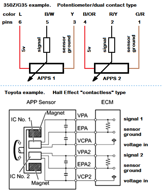
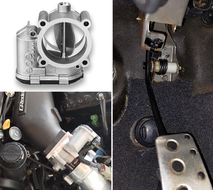
The accelerator pedal position sensor (APPS), also referred to as TPS in some contexts, monitors pedal position and sends signals to the ECU for throttle control in drive-by-wire systems. See examples below for common designs.
Types: There are two main types — potentiometer (resistive) and hall effect (magnetic/non-contact). The wiring and calibration process is generally the same for both, but voltage output behavior and troubleshooting methods differ.
5V supply: Most modern APPS units have two 5V inputs — one for each internal sensor (for redundancy/safety).
Sensor ground: There are typically two sensor grounds — one dedicated to each internal sensor.
Signals: There are two signal wires. Each provides a different voltage output that varies with pedal position. The ECU uses both signals and is programmed to compare them (for plausibility checking and fault detection). In aftermarket/ECU setups, you may configure tables based on these voltages vs. pedal angle.
Troubleshooting:
- Hall effect style: Use an oscilloscope on the signal wire to check for clean square/pulse output.
- Potentiometer style: Use a multimeter to verify smooth voltage sweep (typically ~0.5–4.5V from idle to WOT).
Examples in pictures: Toyota-style pedal assemblies integrate the sensor into the full pedal unit (less preferred for custom swaps due to cost and complexity). The 350Z / G35 style is popular for swaps — it's simple, reliable, easy to remove/modify/weld, and replacement sensors are inexpensive (~$20). Many users adapt these to fit other vehicles (e.g., IS300 pedal arm modifications — see related YouTube videos for details).
Acronyms (common Toyota/Nissan style):
- VCPA — Voltage Constant Pedal Angle (5V supply)
- EPA — Earth Pedal Angle (sensor ground)
- VPA — Voltage Pedal Accelerator (signal wire 1)
- VPA2, EPA2, VCP2 — equivalents for sensor 2 (redundant channel)
Older 4-wire sensors: In aftermarket/cable-drive throttle setups, you may use a simpler 4-wire APPS/TPS. Typically: one 5V supply, one sensor ground, and two signal wires (though many aftermarket ECUs only require one signal wire for basic operation).
• Two main types: potentiometer (resistive) and hall effect (magnetic)
• Dual 5V supplies, dual grounds, dual signals for redundancy
• ECU compares both signals for safety/fault detection
• Preferred style for swaps: 350Z/G35 — easy to modify and cheap to replace
• Toyota-style: integrated pedal + sensor (more expensive/complex for customs)
• 4-wire older/aftermarket: often only one signal used
• Always verify pinout and voltage range against your specific sensor datasheet
Input correct volts vs. pedal angle (%) into your ECU calibration table for accurate throttle response, idle, and drivability.
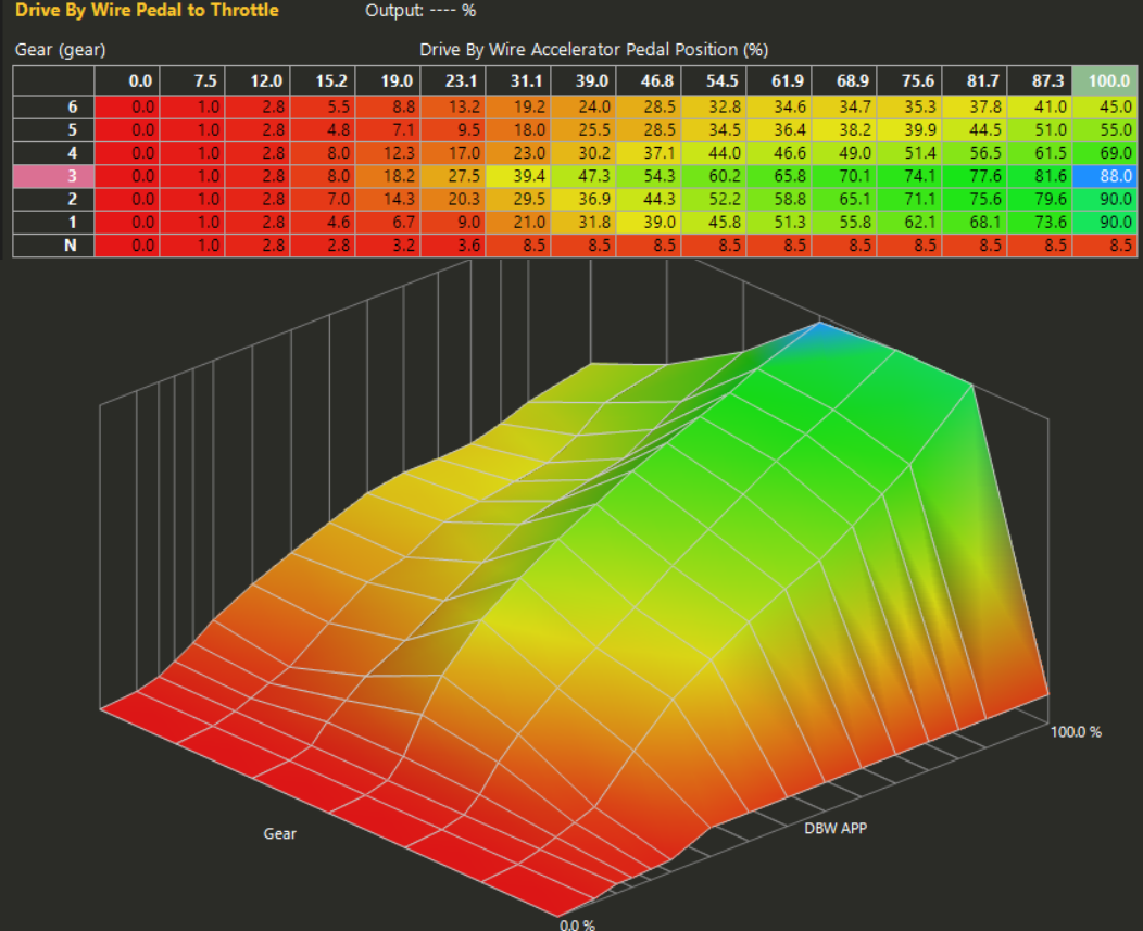
Benefits and custom configuration
Customizing the Accelerator Pedal Position Sensor (APPS) to Throttle Position (TPS) table allows fine-tuned drivability, especially with non-stock throttle bodies or specific performance goals.
The following highlights key benefits and strategies used in a real-world Haltech NSP setup with a significantly oversized throttle body.
- Large Throttle Body Compatibility
One of the primary benefits is the ease of running a larger throttle body on a small to medium sized engine. In this case, the throttle body is approximately 30% larger than the original. While this can cause poor drivability on a standard cable throttle setup, a custom pedal-to-throttle table resolves it by creating a more subtle throttle response at low pedal inputs — making takeoffs smoother and more controllable — while still retaining the full airflow advantages of the larger throttle body. - Less Aggressive Throttle in Higher Gears
By shaping the throttle curve differently across gears (using gear-based tables or conditional logic in the ECU software), throttle opening becomes noticeably less aggressive in the mid-range when in higher gears. This helps prevent accidentally "lugging" the engine by applying excessive throttle too early in high-load, low-RPM situations. - Launch Control Behavior via Neutral Gear Mapping
In the "N" (Neutral) gear position, the pedal curve is intentionally kept relatively flat. This causes the throttle to open very slowly and only to a small percentage even when the pedal is pressed significantly. Because the ECU determines gear based on vehicle movement, the driver can hold the throttle at this launch-friendly position while the car is stationary in 1st gear (ECU still sees Neutral). Once the vehicle begins moving and the ECU registers 1st gear, the throttle table switches to the normal 1st-gear curve — allowing a much quicker and larger throttle opening for a clean, controlled launch.
• Ideal for oversized throttle bodies — tames low-pedal sensitivity while keeping full high-end flow
• Gear-specific shaping reduces mid-range aggression in higher gears (prevents lugging)
• "Neutral" flat curve enables soft throttle on launch → seamless transition to aggressive curve once in gear
• Reference your ECU software (e.g. Haltech NSP) throttle/pedal tables and gear detection logic
• Always test & datalog: Incorrect mapping can cause jerky response, hesitation, or unsafe power delivery
Input precise pedal % vs. desired throttle % values into your calibration tables for best results.
More benefits: "valet mode", "Wife mode", etc
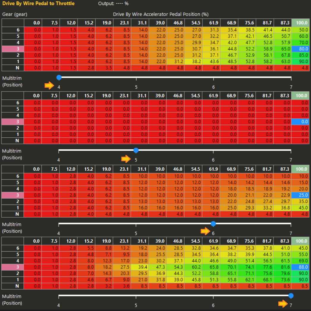
The 12-position dial adjusts Drive-by-Wire (DBW) throttle behavior. Positions 4–7 directly modify the throttle curve (referenced by numbers 4, 5, 6, 7 with arrows in the adjacent chart/image).
- Positions 4 and below: Diagnostic/limp-home modes
- Position 5: Complete throttle shut-off (dead throttle)
- Position 6: Valet / Wife mode – severely limited throttle response
- Position 7 and above: Aggressive / full-performance throttle curve (same as 7)
Positions 8+ maintain the same throttle curve as position 7 but increase boost targets (not shown in this throttle curve chart).
• 1–3: Diagnostic limp-home modes – high fixed idle (2,000–2,500+ RPM), throttle curve same as 4
• 4: Base diagnostic / limp mode
• 5: Dead throttle – no response (park & leave with turbotimer)
• 6: Valet / Wife mode – very tame throttle + limited boost
• 7+: Full aggressive throttle (identical curve from 7 upward)
• Settings 1–3 adjust high idle only (configured on separate Haltech NSP page, not shown here)
• Settings 8+ raise boost targets while keeping throttle curve of position 7
Detailed Mode Descriptions
Diagnostic / Limp-Home Modes (Positions 1–4)
Allows limited driving capability in case of DBW failure. Positions 1, 2, and 3 raise idle to approximately 2,000 RPM, 2,500 RPM, and higher respectively, enabling slow driving home while switching between these settings. Position 4 uses the base throttle curve shown for diagnostic use. These lower positions are not visible in the main throttle curve chart (configured elsewhere in Haltech NSP).
Dead Throttle Mode (Position 5)
Completely disables throttle response. Useful when parking the vehicle and allowing the turbotimer to count down without risk of anyone driving the car (unless they locate the hidden dial).
Valet / Wife Mode (Position 6)
Significantly softens throttle response to make the car much easier and safer to drive. Boost is also limited at this setting, making burnouts or aggressive driving very difficult. Designed for valet drivers or for family members (e.g., wife) who prefer or need a tamer driving experience.
Performance / Aggressive Mode (Position 7+)
Full, sharp throttle response for normal spirited driving. All positions from 7 upward use the same aggressive throttle curve; higher numbers (8+) additionally raise boost targets while throttle mapping remains identical to position 7.
Always verify current dial position and corresponding Haltech NSP settings to ensure intended drivability behavior.
My IS300 DBW upgrade parts
Here are notes on the Drive-By-Wire (DBW) setup components used for the IS300 conversion, focusing on the throttle body, adapters, pedal, and related hardware.
- Porsche 997 GT3 82mm Bosch TB: This is a great TB, my only issue with it is the tiny connector used makes custom wiring difficult.
- Q45 to Bosch 82mm TB adapter: There are many companies that make custom adapters for bolting in the Bosch 82mm TB to whatever manifold you have. I have a Q45 style manifold inlet, so I bought that adapter.
- Deutsch disconnect plug: If you notice in the bottom of the picture near my throttle body, there's a little orange and gray Deutsch 8 pin. I wired this in so I wouldn't struggle with the little Bosch disconnect on the throttle body housing. It also has my IAT sensor connecting through it.
- Infiniti G35 throttle pedal: This sensor and pedal arm is extremely common on eBay and in junkyards. The G35 is one of the most abused cars nowadays, which means many parts end up on eBay. This pedal arm was cheap, and if I need to purchase a replacement sensor it's approximately $20. YouTube video on this upgrade is here.
- Raceworx pipe clamp: I'll admit, I splurged a bit because I wanted a quick-release clamp on the front of my throttle body. It looks sleek, but it doesn't remove easily since it's such a tight fit.
• Porsche 997 GT3 82mm Bosch TB – great performance, tiny connector makes wiring tricky
• Q45 → Bosch 82mm adapter – needed for manifold fitment (many aftermarket options available)
• Deutsch 8-pin disconnect – added for easy service/removal, also carries IAT sensor
• Infiniti G35 pedal assembly – cheap & abundant (eBay/junkyard), replacement sensor ~$20
• Raceworx quick-release clamp – looks great, but very tight and hard to remove
Double-check wiring pinouts, pedal calibration table in ECU, and throttle body compatibility for smooth DBW operation.